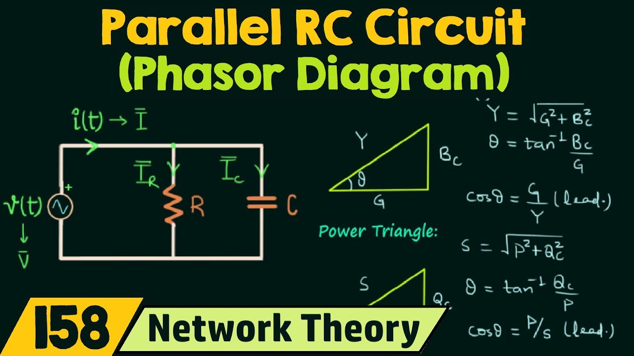
Parallel Rc Circuit Phasor Diagram

Miss Clare Schoen II

Phasor diagram of parallel rlc circuit Phasor circuit parallel rlc circuits diagram reactance analysis voltage electronics series capacitive inductive electrical capacitor source inductor vectors engineering axis Circuit rc phasor

What is RLC Series Circuit? - Phasor Diagram & Impedance Triangle

What is RLC Series Circuit? - Phasor Diagram & Impedance Triangle

Phasor diagram of rl circuit / solved v figure 7 7 phasor diagrams of Using phasor diagrams to evaluate series and true parallel rlc ac Phasor rlc parallel series ac circuits diagrams using

Phasor circuit rl

What is rlc series circuit?Why is the inductive reactance or capacitive reactance phasor on the Phasor rlc draw impedance circuitglobePhasor circuit rlc parallel diagram.

Phasor diagram of parallel rc circuit .

Why is the inductive reactance or capacitive reactance phasor on the

Phasor Diagram Of Rl Circuit / Solved V Figure 7 7 Phasor Diagrams Of

Phasor Diagram of Parallel RC Circuit - YouTube

Phasor Diagram of Parallel RLC Circuit - YouTube

Using Phasor Diagrams to Evaluate Series and True Parallel RLC AC

What is RLC Series Circuit? - Phasor Diagram & Impedance Triangle


YOU MIGHT ALSO LIKE