Or Gate Bjt Circuit Diagram
The bjt circuit shown in figure 2(a) is a "logic nor Electronics projects: how to create a transistor nand gate circuit Bjt amplifier circuit disambiguation
Different Regions of BJT Operation - Electronics… | CircuitBread
Gate 1991 ece small signal voltage gain of given bjt amplifier circuit Gain bjt voltage amplifier signal small circuit gate given Bipolar transistor ebook
Inverter transistor npn bjt transistors mosfet cmos logic signal resistor sparkfun push switching 3v funzionano sono differ dimmer controlling volt
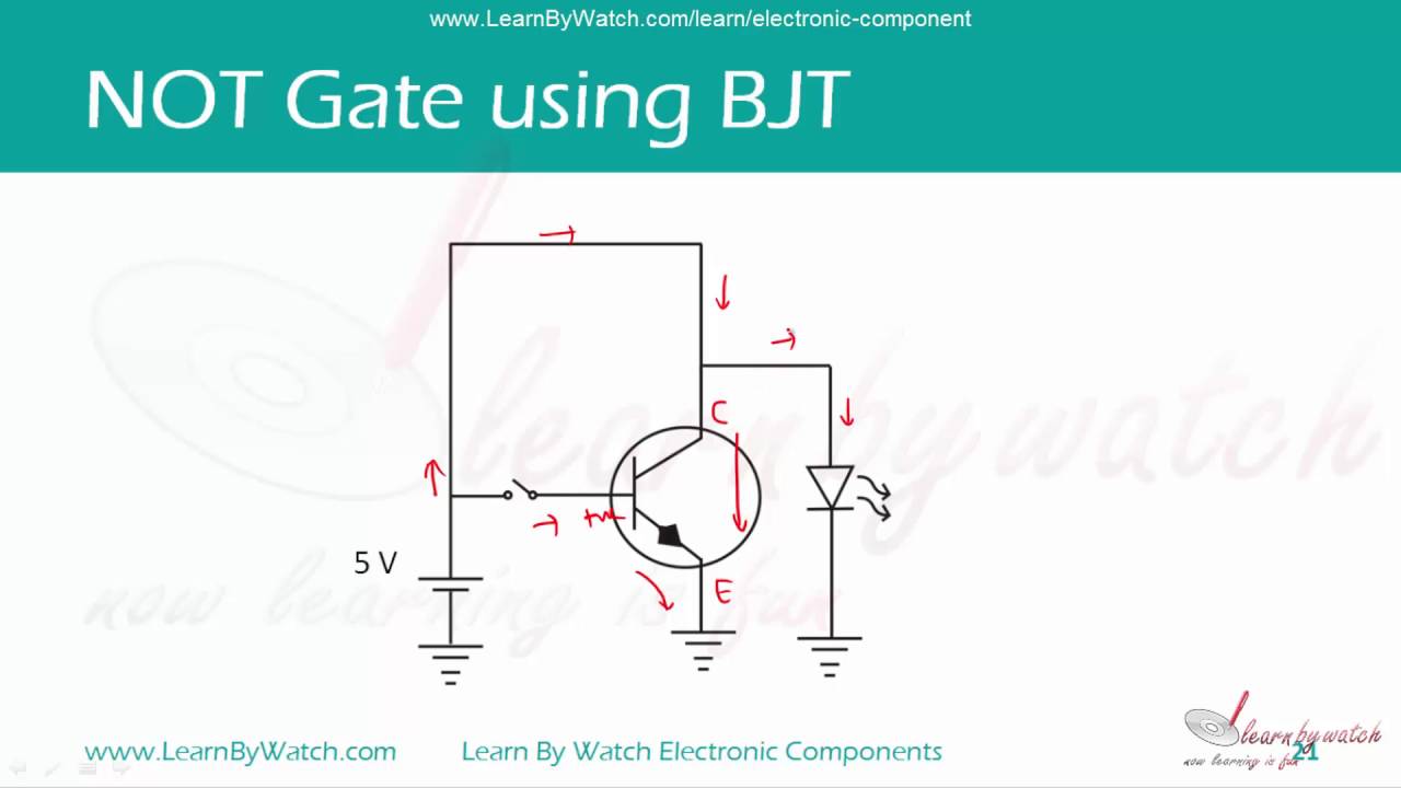
How to make a not gate using bjt or bipolar junction transistorTransistor bipolar bjt amplifier voltages Digital logicGate bjt transistor using make bipolar.
Bjt transistor cutoff saturation voltage relay regionBjt tutorials Bjt inverter circuit gate logic transistor npn usingBjt inverter circuit transfer solved use values shown following find problem been has characteristic.

Bjt npn transistors bipolar transistor junction logic
Bjt transistor rtl resistor nor answered hasnDigital logic Solved use the bjt inverter circuit with its transferNand gate logic transistors circuit transistor bjt using gates input circuits truth table does work electrical tutorial digital series inputs.
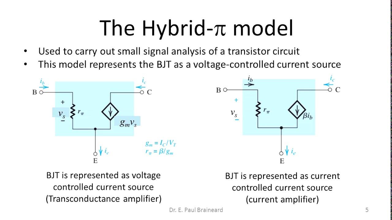
Different regions of bjt operationHybrid pi model of bjt Logic transistor electronics circuit gerbang gates bjt circuits npn inverter transistors rtl electronic schematic gatter ttl nor saturation logika collectorBjt as switch.

Bjt as an amplifier
Nand gate transistor rtl ttl create transistors circuit dummies electronics using projects logic gates better whichQuick and gate using npn bjt circuit with electronics 2n2222 bipolar Npn bjt not logic gate aka inverter circuit using electronics 2n3904Bjt switch.
Bjt circuit switch simulation led drive circuits stack imgur .


